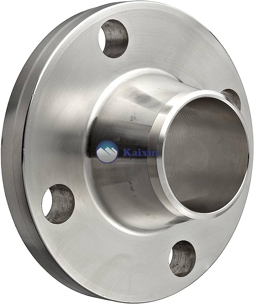
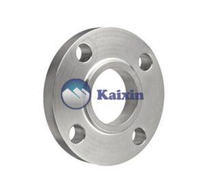
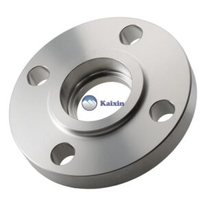
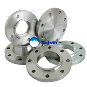
A weld neck flange is a type of flange used for connecting pipelines in a variety of industries, including the oil and gas, chemical, i przemysł petrochemiczny. As the name suggests, the weld neck flange is welded to the end of a pipe, providing a secure and leak-proof connection.
Stainless steel weld neck flanges are widely used due to their excellent corrosion resistance and durability, making them ideal for use in harsh environments such as offshore platforms, chemical processing plants, and gas refineries. These flanges are made of high-grade stainless steel such as 304, 316, Lub 321, and are available in a range of sizes, pressure ratings, and configurations to suit different applications.
One of the main advantages of weld neck flanges is that they provide a strong and stable connection that can withstand high pressures, temperatures, and vibrations. The tapered neck design of the flange helps to reduce stress concentration at the base of the welding joint, making it less susceptible to cracking or failure. Dodatkowo, the raised face of the flange provides a smooth and even sealing surface, reducing the risk of leaks or contamination.
Ogólnie, stainless steel weld neck flanges are a reliable and long-lasting solution for joining pipelines in high-pressure and high-temperature applications. Their resistance to corrosion, chemical attack, and mechanical stress makes them an excellent choice for use in harsh environments, where safety and reliability are crucial.
Spis treści:
- Weld Neck Flanges Specifications
- Applicationsof Blind Flange
- Tworzywo & Grades of Blind Flanges (BLRF)
- Weld Neck Flange Dimensions (Cl. 150/300/900/1500/2500)
- ANSI B16.5 Weld Neck Flange Schedule Chart, Weld Neck Flange Thickness Chart
- Weld Neck Flange Weight Chart
- DIMENSIONAL TOLERANCE WELDING NECK FLANGE
- Standards Referred for WN flange
- Weld Neck Flanges Price List
Weld Neck Flanges Specifications
| Weld Neck Flanges Standards | ANSI/ASME B16.5, B16.47 Seria A & B, B16.48, BS4504, licencjat 10, EN-1092, Z, Kołnierze ANSI, Kołnierze ASME, Kołnierze BS, Kołnierze DIN, ORAZ kołnierze, Kołnierz GOST, ASME/ANSI B16,5/16,36/16,47A/16,47B, MSS S44, ISO70051, JISB2220, BS1560-3.1, API7S-15, API7S-43, API605, EN1092 |
| ASME B16.5 Weld Neck Flanges Size Chart | 1/2″ (15 Uwaga) do 48″ (1200Uwaga) DN10~DN5000 |
| Weld Neck Flanges Pressure Rating ANSI | Klasa 150 LBS, 300 LBS, 600 LBS, 900 LBS, 1500 LBS, 2500 LBS Weld Neck Flanges |
| Powłoka | Czarna farba olejna, Farba antykorozyjna, Ocynkowane, Żółty przezroczysty, Cold and Hot Dip Galvanized Weld Neck Flanges |
| W | 6Bar 10Bar 16Bar 25Bar 40Bar Weld Neck Flanges |
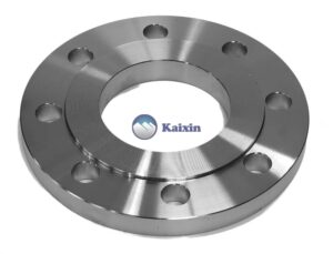
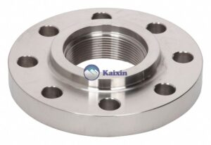
| Most common types of Weld Neck Flanges | Podrobiony / Gwintowane / Pijany / Płyta |
| Typ połączenia/typ czoła kołnierza | Podniesiona twarz (RF), Złącze typu pierścieniowego (RTJ), Płaska twarz (FF), Duży samiec-samica (LMF), Powierzchnia stawu biodrowego (LJF), Mały mężczyzna-kobieta (SMF), Mały język, Duży język & Rowek, Rowek |
| Technika produkcji | · Kute, Obrobione cieplnie i obrabiane maszynowo |
| Test | Spektrograf z odczytem bezpośrednim, Maszyna do prób hydrostatycznych, Detektor rentgenowski, Defektoskop transsoniczny interfejsu użytkownika, Detektor cząstek magnetycznych |
| Sprzęt | Prasa maszynowa, Maszyna do gięcia, Maszyna do pchania, elektryczna maszyna do fazowania, Maszyna do piaskowania itp |
| Weld Neck Flanges Uses & aplikacja | · Uszlachetniacze bitumu.
· Rafinerie ropy ciężkiej. · Energia jądrowa (w większości bez szwu). · Produkty petrochemiczne i kwasy. |
Application of Blind Flange
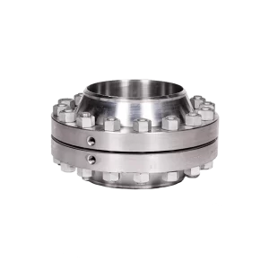
Weld neck flange connections are often found in industrial applications where they are used to join pipes together in order to create larger structures such as boilers or tanks. They can also be used for connecting pumps, zawory, and other pieces of equipment together. Dodatkowo, they can be found in commercial applications such as plumbing systems, where they may be used for joining water lines together or creating drainage systems.
Weld Neck Flange Dimensions (Cl. 150/300/900/1500/2500)
WELDING NECK FLANGE DIMENSIONS IN INCHES
Rysunek wymiarowy kołnierzy łączących zakład
WN CLASS 150 (IN INCH)
Weld neck flange dimensions class 150 (ASME B16.5) in inches
| Flange NPS | Inside
Diameter |
Outside
Diameter |
Bolt Circle
(BC) |
Podniesiona twarz
(R) |
Podniesiona twarz
(RF) |
H | H1 | Podniesiona twarz
Grubość (T) |
T1 | Płaska twarz
Grubość (T2) |
Bolt Hole
(B) |
NIE. of
Bolt Holes |
| 1/2″ | 0.62″ | 3.50″ | 2.38″ | 1.38″ | .063″ | 1.19″ | 0.84″ | 1.88″ | .38″ | 1.82″ | .62″ | 4 |
| 3/4″ | 0.82″ | 3.88″ | 2.75″ | 1.69″ | .063″ | 1.50″ | 1.05″ | 2.06″ | .44″ | 2.00″ | .62″ | 4 |
| 1″ | 1.05″ | 4.25″ | 3.12″ | 2.00″ | .063″ | 1.94″ | 1.32″ | 2.19″ | .50″ | 2.13″ | .62″ | 4 |
| 1-1/4″ | 1.38″ | 4.62″ | 3.50″ | 2.50″ | .063″ | 2.31″ | 1.66″ | 2.25″ | .56″ | 2.19″ | .62″ | 4 |
| 1-1/2″ | 1.61″ | 5.00″ | 3.88″ | 2.88″ | .063″ | 2.56″ | 1.90″ | 2.44″ | .62″ | 2.38″ | .62″ | 4 |
| 2″ | 2.07″ | 6.00″ | 4.75″ | 3.62″ | .063″ | 3.06″ | 2.38″ | 2.50″ | .69″ | 2.44″ | .75″ | 4 |
| 2-1/2″ | 2.47″ | 7.00″ | 5.50″ | 4.12″ | .063″ | 3.56″ | 2.88″ | 2.75″ | .82″ | 2.69″ | .75″ | 4 |
| 3″ | 3.07″ | 7.50″ | 6.00″ | 5.00″ | .063″ | 4.25″ | 3.50″ | 2.75″ | .88″ | 2.69″ | .75″ | 4 |
| 3-1/2″ | 3.55″ | 8.50″ | 7.00″ | 5.50″ | .063″ | 4.81″ | 4.00″ | 2.81″ | .88″ | 2.75″ | .75″ | 8 |
| 4″ | 4.03″ | 9.00″ | 7.50″ | 6.19″ | .063″ | 5.31″ | 4.50″ | 3.00″ | .88″ | 2.94″ | .75″ | 8 |
| 5″ | 5.05″ | 10.00″ | 8.50″ | 7.31″ | .063″ | 6.44″ | 5.56″ | 3.50″ | .88″ | 3.44″ | .88″ | 8 |
| 6″ | 6.07″ | 11.00″ | 9.50″ | 8.50″ | .063″ | 7.56″ | 6.63″ | 3.50″ | .94″ | 3.44″ | .88″ | 8 |
| 8″ | 7.98″ | 13.50″ | 11.75″ | 10.62″ | .063″ | 9.69″ | 8.63″ | 4.00″ | 1.06″ | 3.94″ | .88″ | 8 |
| 10″ | 10.02″ | 16.00″ | 14.25″ | 12.75″ | .063″ | 12.00″ | 10.75″ | 4.00″ | 1.13″ | 3.94″ | 1.00″ | 12 |
| 12″ | 12.00″ | 19.00″ | 17.00″ | 15.00″ | .063″ | 14.38″ | 12.75″ | 4.50″ | 1.19″ | 4.44″ | 1.00″ | 12 |
| 14″ | 13.25″ | 21.00″ | 18.75″ | 16.25″ | .063″ | 15.75″ | 14.00″ | 5.00″ | 1.32″ | 4.94″ | 1.12″ | 12 |
| 16″ | 15.25″ | 23.50″ | 21.25″ | 18.50″ | .063″ | 18.00″ | 16.00″ | 5.00″ | 1.38″ | 4.94″ | 1.12″ | 16 |
| 18″ | 17.25″ | 25.00″ | 22.75″ | 21.00″ | .063″ | 19.88″ | 18.00″ | 5.50″ | 1.50″ | 5.44″ | 1.25″ | 16 |
| 20″ | 19.25″ | 27.50″ | 25.00″ | 23.00″ | .063″ | 22.00″ | 20.00″ | 5.69″ | 1.63″ | 5.63″ | 1.25″ | 20 |
| 22″ | 21.25″ | 29.50″ | 27.25″ | 25.25″ | .063″ | 24.25″ | 22.00″ | 5.88″ | 1.75″ | 5.82″ | 1.38″ | 20 |
| 24″ | 23.25″ | 32.00″ | 29.50″ | 27.25″ | .063″ | 26.12″ | 24.00″ | 6.00″ | 1.82″ | 5.94″ | 1.38″ | 20 |
WN CLASS 300 (IN INCH)
Weld neck flange dimensions class 300 (ASME B16.5) in inches
| Flange NPS | Inside
Diameter |
Outside
Diameter |
Bolt Circle
(BC) |
Podniesiona twarz
(R) |
Podniesiona twarz
(RF) |
H | H1 | Podniesiona twarz
Grubość (T) |
T1 | Płaska twarz
Grubość (T2) |
Bolt Hole
(B) |
NIE. of
Bolt Holes |
| 1/2″ | 0.62″ | 3.75″ | 2.62″ | 1.38″ | .063″ | 1.50″ | 0.84″ | 2.06″ | .50″ | 2.00″ | 0.62″ | 4 |
| 3/4″ | 0.82″ | 4.62″ | 3.25″ | 1.69″ | .063″ | 1.88″ | 1.05″ | 2.25″ | .56″ | 2.19″ | 0.75″ | 4 |
| 1″ | 1.05″ | 4.88″ | 3.50″ | 2.00″ | .063″ | 2.12″ | 1.32″ | 2.44″ | .63″ | 2.38″ | 0.75″ | 4 |
| 1-1/4″ | 1.38″ | 5.25″ | 3.88″ | 2.50″ | .063″ | 2.50″ | 1.66″ | 2.56″ | .69″ | 2.50″ | 0.75″ | 4 |
| 1-1/2″ | 1.61″ | 6.12″ | 4.50″ | 2.88″ | .063″ | 2.75″ | 1.90″ | 2.69″ | .75″ | 2.63″ | 0.88″ | 4 |
| 2″ | 2.07″ | 6.50″ | 5.00″ | 3.62″ | .063″ | 3.31″ | 2.38″ | 2.75″ | .82″ | 2.69″ | 0.75″ | 8 |
| 2-1/2″ | 2.47″ | 7.50″ | 5.88″ | 4.12″ | .063″ | 3.94″ | 2.88″ | 3.00″ | .94″ | 2.94″ | 0.88″ | 8 |
| 3″ | 3.07″ | 8.25″ | 6.62″ | 5.00″ | .063″ | 4.62″ | 3.50″ | 3.12″ | 1.06″ | 3.06″ | 0.88″ | 8 |
| 3-1/2″ | 3.55″ | 9.00″ | 7.25″ | 5.50″ | .063″ | 5.25″ | 4.00″ | 3.19″ | 1.13″ | 3.13″ | 0.88″ | 8 |
| 4″ | 4.03″ | 10.00″ | 7.88″ | 6.19″ | .063″ | 5.75″ | 4.50″ | 3.38″ | 1.19″ | 3.32″ | 0.88″ | 8 |
| 5″ | 5.05″ | 11.00″ | 9.25″ | 7.31″ | .063″ | 7.00″ | 5.56″ | 3.88″ | 1.32″ | 3.82″ | 0.88″ | 8 |
| 6″ | 6.07″ | 12.50″ | 10.62″ | 8.50″ | .063″ | 8.12″ | 6.63″ | 3.88″ | 1.38″ | 3.82″ | 0.88″ | 12 |
| 8″ | 7.98″ | 15.00″ | 13.00″ | 10.62″ | .063″ | 10.25″ | 8.63″ | 4.38″ | 1.56″ | 4.32″ | 1.00″ | 12 |
| 10″ | 10.02″ | 17.50″ | 15.25″ | 12.75″ | .063″ | 12.62″ | 10.75″ | 4.62″ | 1.82″ | 4.56″ | 1.12″ | 16 |
| 12″ | 12.00″ | 20.50″ | 17.75″ | 15.00″ | .063″ | 14.75″ | 12.75″ | 5.12″ | 1.94″ | 5.06″ | 1.25″ | 16 |
| 14″ | 13.25″ | 23.00″ | 20.25″ | 16.25″ | .063″ | 16.75″ | 14.00″ | 5.62″ | 2.06″ | 5.56″ | 1.25″ | 20 |
| 16″ | 15.25″ | 25.50″ | 22.50″ | 18.50″ | .063″ | 19.00″ | 16.00″ | 5.75″ | 2.19″ | 5.69″ | 1.38″ | 20 |
| 18″ | 17.25″ | 28.00″ | 24.75″ | 21.00″ | .063″ | 21.00″ | 18.00″ | 6.25″ | 2.32″ | 6.19″ | 1.38″ | 24 |
| 20″ | 19.25″ | 30.50″ | 27.00″ | 23.00″ | .063″ | 23.12″ | 20.00″ | 6.38″ | 2.44″ | 6.32″ | 1.38″ | 24 |
| 22″ | 21.25″ | 33.00″ | 29.25″ | 25.25″ | .063″ | 25.25″ | 22.00″ | 6.50″ | 2.57″ | 6.44″ | 1.62″ | 24 |
| 24″ | 23.25″ | 36.00″ | 32.0″ | 27.25″ | .063″ | 27.62″ | 24.00″ | 6.62″ | 2.69″ | 6.56″ | 1.62″ | 24 |
WN CLASS 400 (IN INCH)
Weld neck flange dimensions class 400 (ASME B16.5) in inches
| Flange NPS | Inside
Diameter |
Outside
Diameter |
Bolt Circle
(BC) |
Podniesiona twarz
(R) |
Podniesiona twarz
(RF) |
H | H1 | Podniesiona twarz
Grubość (T) |
T1 | Płaska twarz
Grubość (T2) |
Bolt Hole
(B) |
NIE. of
Bolt Holes |
| 1/2″ | .55″ | 3.75″ | 2.62″ | 1.38″ | .250″ | 1.50″ | 0.84″ | 2.31″ | 0.56″ | 2.06″ | 0.62″ | 4 |
| 3/4″ | .74″ | 4.62″ | 3.25″ | 1.69″ | .250″ | 1.88″ | 1.05″ | 2.50″ | 0.62″ | 2.25″ | 0.75″ | 4 |
| 1″ | .96″ | 4.88″ | 3.50″ | 2.00″ | .250″ | 2.12″ | 1.32″ | 2.69″ | 0.69″ | 2.44″ | 0.75″ | 4 |
| 1-1/4″ | 1.28″ | 5.25″ | 3.88″ | 2.50″ | .250″ | 2.50″ | 1.66″ | 2.87″ | 0.81″ | 2.62″ | 0.75″ | 4 |
| 1-1/2″ | 1.50″ | 6.12″ | 4.50″ | 2.88″ | .250″ | 2.75″ | 1.90″ | 3.00″ | 0.88″ | 2.75″ | 0.88″ | 4 |
| 2″ | 1.94″ | 6.50″ | 5.00″ | 3.62″ | .250″ | 3.31″ | 2.38″ | 3.13″ | 1.00″ | 2.88″ | 0.75″ | 8 |
| 2-1/2″ | 2.32″ | 7.50″ | 5.88″ | 4.12″ | .250″ | 3.94″ | 2.88″ | 3.37″ | 1.12″ | 3.12″ | 0.88″ | 8 |
| 3″ | 2.90″ | 8.25″ | 6.62″ | 5.00″ | .250″ | 4.62″ | 3.50″ | 3.50″ | 1.25″ | 3.25″ | 0.88″ | 8 |
| 3-1/2″ | 3.36″ | 9.00″ | 7.25″ | 5.50″ | .250″ | 5.25″ | 4.00″ | 3.63″ | 1.38″ | 3.38″ | 1.00″ | 8 |
| 4″ | 3.83″ | 10.00″ | 7.88″ | 6.19″ | .250″ | 5.75″ | 4.50″ | 3.75″ | 1.38″ | 3.50″ | 1.00″ | 8 |
| 5″ | 4.81″ | 11.00″ | 9.25″ | 7.31″ | .250″ | 7.00″ | 5.56″ | 4.25″ | 1.50″ | 4.00″ | 1.00″ | 8 |
| 6″ | 5.76″ | 12.50″ | 10.62″ | 8.50″ | .250″ | 8.12″ | 6.63″ | 4.31″ | 1.62″ | 4.06″ | 1.00″ | 12 |
| 8″ | 7.63″ | 15.00″ | 13.00″ | 10.62″ | .250″ | 10.25″ | 8.63″ | 4.87″ | 1.88″ | 4.62″ | 1.12″ | 12 |
| 10″ | 9.75″ | 17.50″ | 15.25″ | 12.75″ | .250″ | 12.62″ | 10.75″ | 5.13″ | 2.12″ | 4.88″ | 1.25″ | 16 |
| 12″ | 11.75″ | 20.50″ | 17.75″ | 15.00″ | .250″ | 14.75″ | 12.75″ | 5.63″ | 2.25″ | 5.38″ | 1.38″ | 16 |
| 14″ | 13.00″ | 23.00″ | 20.25″ | 16.25″ | .250″ | 16.75″ | 14.00″ | 6.13″ | 2.38″ | 5.88″ | 1.38″ | 20 |
| 16″ | 15.00″ | 25.50″ | 22.50″ | 18.50″ | .250″ | 19.00″ | 16.00″ | 6.25″ | 2.50″ | 6.00″ | 1.50″ | 20 |
| 18″ | 17.00″ | 28.00″ | 24.75″ | 21.00″ | .250″ | 21.00″ | 18.00″ | 6.75″ | 2.62″ | 6.50″ | 1.50″ | 24 |
| 20″ | 19.00″ | 30.50″ | 27.00″ | 23.00″ | .250″ | 23.12″ | 20.00″ | 6.87″ | 2.75″ | 6.62″ | 1.62″ | 24 |
| 22″ | 21.00″ | 33.00″ | 29.25″ | 25.25″ | .250″ | 25.25″ | 22.00″ | 7.00″ | 2.88″ | 6.75″ | 1.75″ | 24 |
| 24″ | 23.00″ | 36.00″ | 32.00″ | 27.25″ | .250″ | 27.62″ | 24.00″ | 7.13″ | 3.00″ | 6.88″ | 1.88″ | 24 |
WN CLASS 600 (IN INCH)
Weld neck flange dimensions class 600 (ASME B16.5) in inches
| Flange NPS | Inside
Diameter |
Outside
Diameter |
Bolt Circle
(BC) |
Podniesiona twarz
(R) |
Podniesiona twarz
(RF) |
H | H1 | Podniesiona twarz
Grubość (T) |
T1 | Płaska twarz
Grubość (T2) |
Bolt Hole
(B) |
NIE. of
Bolt Holes |
| 1/2″ | 0.55″ | 3.75″ | 2.62″ | 1.38″ | .250″ | 1.50″ | 0.84″ | 2.31″ | 0.56″ | 2.06″ | 0.62″ | 4 |
| 3/4″ | 0.74″ | 4.62″ | 3.25″ | 1.69″ | .250″ | 1.88″ | 1.05″ | 2.50″ | 0.62″ | 2.25″ | 0.75″ | 4 |
| 1″ | 0.96″ | 4.88″ | 3.50″ | 2.00″ | .250″ | 2.12″ | 1.32″ | 2.69″ | 0.69″ | 2.44″ | 0.75″ | 4 |
| 1-1/4″ | 1.28″ | 5.25″ | 3.88″ | 2.50″ | .250″ | 2.50″ | 1.66″ | 2.87″ | 0.81″ | 2.62″ | 0.75″ | 4 |
| 1-1/2″ | 1.50″ | 6.12″ | 4.50″ | 2.88″ | .250″ | 2.75″ | 1.90″ | 3.00″ | 0.88″ | 2.75″ | 0.88″ | 4 |
| 2″ | 1.94″ | 6.50″ | 5.00″ | 3.62″ | .250″ | 3.31″ | 2.38″ | 3.13″ | 1.00″ | 2.88″ | 0.75″ | 8 |
| 2-1/2″ | 2.32″ | 7.50″ | 5.88″ | 4.12″ | .250″ | 3.94″ | 2.88″ | 3.37″ | 1.12″ | 3.12″ | 0.88″ | 8 |
| 3″ | 2.90″ | 8.25″ | 6.62″ | 5.00″ | .250″ | 4.62″ | 3.50″ | 3.50″ | 1.25″ | 3.25″ | 0.88″ | 8 |
| 3-1/2″ | 3.36″ | 9.00″ | 7.25″ | 5.50″ | .250″ | 5.25″ | 4.00″ | 3.63″ | 1.38″ | 3.38″ | 1.00″ | 8 |
| 4″ | 3.83″ | 10.75″ | 8.50″ | 6.19″ | .250″ | 6.00″ | 4.50″ | 4.25″ | 1.5″ | 4.00″ | 1.00″ | 8 |
| 5″ | 4.81″ | 13.00″ | 10.50″ | 7.31″ | .250″ | 7.44″ | 5.56″ | 4.75″ | 1.75″ | 4.50″ | 1.12″ | 8 |
| 6″ | 5.76″ | 14.00″ | 11.50″ | 8.50″ | .250″ | 8.75″ | 6.63″ | 4.87″ | 1.88″ | 4.62″ | 1.12″ | 12 |
| 8″ | 7.63″ | 16.50″ | 13.75″ | 10.62″ | .250″ | 10.75″ | 8.63″ | 5.50″ | 2.19″ | 5.25″ | 1.25″ | 12 |
| 10″ | 9.75″ | 20.00″ | 17.00″ | 12.75″ | .250″ | 13.5″ | 10.75″ | 6.25″ | 2.50″ | 6.00″ | 1.38″ | 16 |
| 12″ | 11.75″ | 22.00″ | 19.25″ | 15.00″ | .250″ | 15.75″ | 12.75″ | 6.37″ | 2.62″ | 6.12″ | 1.38″ | 20 |
| 14″ | 13.00″ | 23.75″ | 20.75″ | 16.25″ | .250″ | 17.00″ | 14.00″ | 6.75″ | 2.75″ | 6.50″ | 1.50″ | 20 |
| 16″ | 15.00″ | 27.00″ | 23.75″ | 18.50″ | .250″ | 19.50″ | 16.00″ | 7.25″ | 3.00″ | 7.00″ | 1.62″ | 20 |
| 18″ | 17.00″ | 29.25″ | 25.75″ | 21.00″ | .250″ | 21.50″ | 18.00″ | 7.50″ | 3.25″ | 7.25″ | 1.75″ | 20 |
| 20″ | 19.00″ | 32.00″ | 28.50″ | 23.00″ | .250″ | 24.00″ | 20.00″ | 7.75″ | 3.50″ | 7.50″ | 1.75″ | 24 |
| 22″ | 21.00″ | 34.25″ | 30.63″ | 25.25″ | .250″ | 26.25″ | 22.00″ | 8.00″ | 3.75″ | 7.75″ | 1.75″ | 24 |
| 24″ | 23.00″ | 37.00″ | 33.00″ | 27.25″ | .250″ | 28.25″ | 24.00″ | 8.25″ | 4.00″ | 8.00″ | 2.00″ | 24 |
WN CLASS 900 (IN INCH)
Weld neck flange dimensions class 900 (ASME B16.5) in inches
| lange NPS | Inside
Diameter |
Outside
Diameter |
Bolt Circle
(BC) |
Podniesiona twarz
(R) |
Podniesiona twarz
(RF) |
H | H1 | Podniesiona twarz
Grubość (T) |
T1 | Płaska twarz
Grubość (T2) |
Bolt Hole
(B) |
NIE. of
Bolt Holes |
| 3″ | 2.90″ | 9.50″ | 7.50″ | 5.00″ | .250″ | 5.00″ | 3.50″ | 4.25″ | 1.50″ | 4.00″ | 1.00″ | 8 |
| 4″ | 3.83″ | 11.50″ | 9.25″ | 6.19″ | .250″ | 6.25″ | 4.50″ | 4.75″ | 1.75″ | 4.50″ | 1.25″ | 8 |
| 5″ | 4.81″ | 13.75″ | 11.00″ | 7.31″ | .250″ | 7.50″ | 5.56″ | 5.25″ | 3.00″ | 5.00″ | 1.38″ | 8 |
| 6″ | 5.76″ | 15.00″ | 12.50″ | 8.50″ | .250″ | 9.25″ | 6.63″ | 5.75″ | 2.19″ | 5.50″ | 1.25″ | 12 |
| 8″ | 7.63″ | 18.50″ | 15.50″ | 10.63″ | .250″ | 11.75″ | 8.63″ | 6.63″ | 2.50″ | 6.38″ | 1.50″ | 12 |
| 10″ | 9.75″ | 21.50″ | 18.50″ | 12.75″ | .250″ | 14.50″ | 10.75″ | 7.50″ | 2.75″ | 7.25″ | 1.50″ | 16 |
| 12″ | 11.75″ | 24.00″ | 21.00″ | 15.00″ | .250″ | 16.50″ | 12.75″ | 8.13″ | 3.13″ | 7.88″ | 1.50″ | 20 |
| 14″ | 13.00″ | 25.25″ | 22.00″ | 16.25″ | .250″ | 17.75″ | 14.00″ | 8.63″ | 3.38″ | 8.38″ | 1.63″ | 20 |
| 16″ | 15.00″ | 27.75″ | 24.25″ | 18.50″ | .250″ | 20.00″ | 16.00″ | 8.75″ | 3.50″ | 8.50″ | 1.75″ | 20 |
| 18″ | 17.00″ | 31.00″ | 27.00″ | 21.00″ | .250″ | 22.25″ | 18.00″ | 9.25″ | 4.00″ | 9.00″ | 2.00″ | 20 |
| 20″ | 19.00″ | 33.75″ | 29.50″ | 23.00″ | .250″ | 24.50″ | 20.00″ | 10.00″ | 4.25″ | 9.75″ | 2.13″ | 20 |
| 24″ | 23.00″ | 41.00″ | 35.50″ | 27.25″ | .250″ | 29.50″ | 24.00″ | 11.75″ | 5.50″ | 11.50″ | 2.63″ | 20 |
WN CLASS 1500 (IN INCH)
Weld neck flange dimensions class 1500 (ASME B16.5) in inches
| Flange NPS | Inside
Diameter |
Outside
Diameter |
Bolt Circle
(BC) |
Podniesiona twarz
(R) |
Podniesiona twarz
(RF) |
H | H1 | Podniesiona twarz
Grubość (T) |
T1 | Płaska twarz
Grubość (T2) |
Bolt Hole
(B) |
NIE. of
Bolt Holes |
| 1/2″ | 0.55″ | 4.75″ | 3.25″ | 1.38″ | .250″ | 1.50″ | 0.84″ | 2.63″ | 0.88″ | 2.38″ | 0.88″ | 4 |
| 3/4″ | 0.74″ | 5.13″ | 3.50″ | 1.69″ | .250″ | 1.75″ | 1.05″ | 3.00″ | 1.00″ | 2.75″ | 0.88″ | 4 |
| 1″ | 0.96″ | 5.88″ | 4.00″ | 2.00″ | .250″ | 2.06″ | 1.32″ | 3.13″ | 1.13″ | 2.88″ | 1.00″ | 4 |
| 1-1/4″ | 1.28″ | 6.25″ | 4.38″ | 2.50″ | .250″ | 2.50″ | 1.66″ | 3.13″ | 1.13″ | 2.88″ | 1.00″ | 4 |
| 1-1/2″ | 1.50″ | 7.00″ | 4.88″ | 2.88″ | .250″ | 2.75″ | 1.90″ | 3.50″ | 1.25″ | 3.25″ | 1.13″ | 4 |
| 2″ | 1.94″ | 8.50″ | 6.50″ | 3.63″ | .250″ | 4.13″ | 2.38″ | 4.25″ | 1.50″ | 4.00″ | 1.00″ | 8 |
| 2-1/2″ | 2.32″ | 9.63″ | 7.50″ | 4.13″ | .250″ | 4.88″ | 2.88″ | 4.38″ | 1.63″ | 4.13″ | 1.13″ | 8 |
| 3″ | 2.90″ | 10.50″ | 8.00″ | 5.00″ | .250″ | 5.25″ | 3.50″ | 4.88″ | 1.88″ | 4.63″ | 1.25″ | 8 |
| 4″ | 3.83″ | 12.25″ | 9.50″ | 6.19″ | .250″ | 6.38″ | 4.50″ | 5.13″ | 2.13″ | 4.88″ | 1.38″ | 8 |
| 5″ | 4.81″ | 14.75″ | 11.50″ | 7.31″ | .250″ | 7.75″ | 5.56″ | 6.38″ | 2.88″ | 6.13″ | 1.63″ | 8 |
| 6″ | 5.76″ | 15.50″ | 12.50″ | 8.50″ | .250″ | 9.00″ | 6.63″ | 7.00″ | 3.25″ | 6.75″ | 1.50″ | 12 |
| 8″ | 7.63″ | 19.00″ | 15.50″ | 10.63″ | .250″ | 11.50″ | 8.63″ | 8.63″ | 3.63″ | 8.38″ | 1.75″ | 12 |
| 10″ | 9.75″ | 23.00″ | 19.00″ | 12.75″ | .250″ | 14.50″ | 10.75″ | 10.25″ | 4.25″ | 10.00″ | 2.00″ | 12 |
| 12″ | 11.75″ | 26.50″ | 22.50″ | 15.00″ | .250″ | 17.75″ | 12.75″ | 11.38″ | 4.88″ | 11.13″ | 2.13″ | 16 |
| 14″ | 13.00″ | 29.50″ | 25.00″ | 16.25″ | .250″ | 19.50″ | 14.00″ | 12.00″ | 5.25″ | 11.75″ | 2.38″ | 16 |
| 16″ | 15.00″ | 32.50″ | 27.75″ | 18.50″ | .250″ | 21.75″ | 16.00″ | 12.50″ | 5.75″ | 12.25″ | 2.63″ | 16 |
| 18″ | 17.00″ | 36.00″ | 30.50″ | 21.00″ | .250″ | 23.50″ | 18.00″ | 13.13″ | 6.38″ | 12.88″ | 2.88″ | 16 |
| 20″ | 19.00″ | 38.75″ | 32.75″ | 23.00″ | .250″ | 25.25″ | 20.00″ | 14.25″ | 7.00″ | 14.00″ | 3.13″ | 16 |
| 24″ | 23.00″ | 46.00″ | 39.00″ | 27.25″ | .250″ | 30.00″ | 24.00″ | 16.25″ | 8.00″ | 16.00″ | 3.63″ | 16 |
WN CLASS 2500 (IN INCH)
Weld neck flange dimensions class 2500 (ASME B16.5) in inches
| Flange NPS | Inside
Diameter |
Outside
Diameter |
Bolt Circle
(BC) |
Podniesiona twarz
(R) |
Podniesiona twarz
(RF) |
H | H1 | Podniesiona twarz
Grubość (T) |
T1 | Płaska twarz
Grubość (T2) |
Bolt Hole
(B) |
NIE. of
Bolt Holes |
| 1/2″ | 0.55″ | 5.25″ | 3.50″ | 1.38″ | .250″ | 1.69″ | 0.84″ | 3.13″ | 1.19″ | 2.88″ | 0.88″ | 4 |
| 3/4″ | 0.74″ | 5.50″ | 3.75″ | 1.69″ | .250″ | 2.00″ | 1.05″ | 3.38″ | 1.25″ | 3.13″ | 0.88″ | 4 |
| 1″ | 0.96″ | 6.25″ | 4.25″ | 2.00″ | .250″ | 2.25″ | 1.32″ | 3.75″ | 1.38″ | 3.50″ | 1.00″ | 4 |
| 1-1/4″ | 1.28″ | 7.25″ | 5.13″ | 2.50″ | .250″ | 2.88″ | 1.66″ | 4.00″ | 1.50″ | 3.75″ | 1.13″ | 4 |
| 1-1/2″ | 1.50″ | 8.00″ | 5.75″ | 2.88″ | .250″ | 3.13″ | 1.90″ | 4.63″ | 1.75″ | 4.38″ | 1.25″ | 4 |
| 2″ | 1.94″ | 9.25″ | 6.75″ | 3.63″ | .250″ | 3.75″ | 2.38″ | 5.25″ | 2.00″ | 5.00″ | 1.13″ | 8 |
| 2-1/2″ | 2.32″ | 10.50″ | 7.75″ | 4.13″ | .250″ | 4.50″ | 2.88″ | 5.88″ | 2.25″ | 5.63″ | 1.25″ | 8 |
| 3″ | 2.90″ | 12.00″ | 9.00″ | 5.00″ | .250″ | 5.25″ | 3.50″ | 6.88″ | 2.63″ | 6.63″ | 1.38″ | 8 |
| 4″ | 3.83″ | 14.00″ | 10.75″ | 6.19″ | .250″ | 6.50″ | 4.50″ | 7.75″ | 3.00″ | 7.50″ | 1.63″ | 8 |
| 5″ | 4.81″ | 16.50″ | 12.75″ | 7.31″ | .250″ | 8.00″ | 5.56″ | 9.25″ | 3.63″ | 9.00″ | 1.88″ | 8 |
| 6″ | 5.76″ | 19.00″ | 14.50″ | 8.50″ | .250″ | 9.25″ | 6.63″ | 11.00″ | 4.25″ | 10.75″ | 2.13″ | 8 |
| 8″ | 7.63″ | 21.75″ | 17.25″ | 10.63″ | .250″ | 12.00″ | 8.63″ | 12.75″ | 5.00″ | 12.50″ | 2.13″ | 12 |
| 10″ | 9.75″ | 26.50″ | 21.25″ | 12.75″ | .250″ | 14.75″ | 10.75″ | 16.75″ | 6.50″ | 16.50″ | 2.63″ | 12 |
| 12″ | 11.75″ | 30.00″ | 24.38″ | 15.00″ | .250″ | 17.38″ | 12.75″ | 18.50″ | 7.25″ | 18.25″ | 2.88″ | 12 |
ANSI B16.5 Weld Neck Flange Schedule Chart, Weld Neck Flange Thickness Chart
| WELDING NECK FLANGES BORES (in inchines) | ||||||||||||||
| Nom
Pipe Rozmiar |
Outside
Diam |
Sched
10 |
Sched
20 |
Sched
30 |
Std.
Wall |
Sched
40 |
Sched
60 |
Extra
Strong |
Sched
80 |
Sched
100 |
Sched
120 |
Sched
140 |
Sched
160 |
Double
Extra Strong |
| 1/2" | 0.840 | 0.674 | – | – | 0.622 | 0.622 | – | 0.546 | 0.546 | – | – | – | 0.464 | 0.252 |
| 3/4" | 1.050 | 0.884 | – | – | 0.824 | 0.824 | – | 0.742 | 0.742 | – | – | – | 0.612 | 0.434 |
| 1" | 1.315 | 1.097 | – | – | 1.049 | 1.049 | – | 0.957 | 0.957 | – | – | – | 0.815 | 0.599 |
| 1.1/4" | 1.660 | 1.442 | – | – | 1.380 | 1.380 | – | 1.278 | 1.278 | – | – | – | 1.160 | 0.896 |
| 1.1/2" | 1.900 | 1.682 | – | – | 1.610 | 1.610 | – | 1.500 | 1.500 | – | – | – | 1.338 | 1.100 |
| 2" | 2.375 | 2.157 | – | – | 2.067 | 2.067 | – | 1.939 | 1.939 | – | – | – | 1.687 | 1.503 |
| 2.1/2" | 2.875 | 2.635 | – | – | 2.469 | 2.469 | – | 2.323 | 2.323 | – | – | – | 2.125 | 1.771 |
| 3" | 3.500 | 3.260 | – | – | 3.068 | 3.068 | – | 2.900 | 2.900 | – | – | – | 2.624 | 2.300 |
| 3-1/2" | 4.000 | 3.760 | – | – | 3.548 | 3.548 | – | 3.364 | 3.364 | – | – | – | – | 2.728 |
| 4" | 4.500 | 4.260 | – | – | 4.026 | 4.026 | – | 3.826 | 3.826 | – | 3.624 | – | 3.438 | 3.152 |
| 5" | 5.563 | 5.295 | – | – | 5.047 | 5.047 | – | 4.813 | 4.813 | – | 4.563 | – | 4.313 | 4.063 |
| 6" | 6.625 | 6.357 | – | – | 6.065 | 6.065 | – | 5.761 | 5.761 | – | 5.501 | – | 5.187 | 4.897 |
| 8" | 8.625 | 8.329 | 8.125 | 8.071 | 7.981 | 7.981 | 7.813 | 7.625 | 7.625 | 7.437 | 7.187 | 7.001 | 6.813 | 6.875 |
| 10" | 10.750 | 10.420 | 10.250 | 10.136 | 10.020 | 10.020 | 9.750 | 9.750 | 9.562 | 9.312 | 9.062 | 8.750 | 8.500 | 8.750 |
| 12" | 12.750 | 12.390 | 12.250 | 12.090 | 12.000 | 11.938 | 11.626 | 11.750 | 11.374 | 11.062 | 10.750 | 10.500 | 10.126 | 10.750 |
| 14" | 14.000 | 13.500 | 13.376 | 13.250 | 13.250 | 13.124 | 12.812 | 13.000 | 12.500 | 12.124 | 11.814 | 11.500 | 11.188 | – |
| 16" | 16.000 | 15.500 | 15.376 | 15.250 | 15.250 | 15.000 | 14.688 | 15.000 | 14.312 | 13.938 | 13.564 | 13.124 | 12.812 | – |
| 18" | 18.000 | 17.500 | 17.376 | 17.124 | 17.250 | 16.876 | 16.500 | 17.000 | 16.124 | 15.688 | 15.250 | 14.876 | 14.438 | – |
| 20" | 20.000 | 19.500 | 19.250 | 19.000 | 19.250 | 18.812 | 18.376 | 19.000 | 17.938 | 17.438 | 17.000 | 16.500 | 16.062 | – |
| 24" | 24.000 | 23.500 | 23.250 | 22.876 | 23.250 | 22.624 | 22.062 | 23.000 | 21.562 | 20.938 | 20.376 | 19.876 | 19.312 | – |
| 30" | 30.000 | 29.376 | 29.000 | 28.750 | 29.250 | – | – | 29.000 | – | – | – | – | – | – |
| 36" | 36.000 | 35.376 | 35.000 | 34.750 | 35.250 | 34.500 | – | 35.000 | – | – | – | – | – | – |
| 42" | 42.000 | – | – | – | 41.250 | – | – | 41.000 | – | |||||
Weld Neck Flange Weight Chart
| ANSI B16.5 WELD NECK FLANGES WEIGHT (KGS) | ||||||||||||||||||
| Nom
Pipe Rozmiar |
150# | 300# | 600# | 900# | 1500# | 2500# | ||||||||||||
| WN | S/O | B/K | WN | S/O | B/K | WN | S/O | B/K | WN | S/O | B/K | WN | S/O | B/K | WN | S/O | B/K | |
| 1/2" | 0.7 | 0.4 | 0.5 | 0.8 | 0.7 | 0.8 | 0.9 | 0.8 | 0.8 | 2.1 | 1.8 | 1.9 | 2.1 | 1.8 | 1.9 | 3.2 | 3 | 3 |
| 3/4" | 0.8 | 0.7 | 0.8 | 1.4 | 1.2 | 1.2 | 1.6 | 1.4 | 1.4 | 2.7 | 2.4 | 2.7 | 2.7 | 2.4 | 2.7 | 3.6 | 4 | 4.5 |
| 1" | 1.1 | 0.8 | 0.9 | 1.7 | 1.4 | 1.5 | 1.9 | 1.7 | 1.7 | 3.9 | 3.6 | 3.7 | 3.9 | 3.6 | 3.7 | 5.4 | 5 | 5 |
| 1.1/4" | 1.5 | 1.2 | 1.3 | 2.2 | 1.8 | 2 | 2.6 | 2.1 | 2.4 | 4.5 | 4.1 | 4.3 | 4.5 | 4.1 | 4.3 | 7.8 | 8 | 8 |
| 1.1/2" | 1.8 | 1.4 | 1.6 | 3.2 | 2.7 | 2.9 | 3.6 | 3.1 | 3.4 | 6.2 | 5.4 | 5.9 | 6.2 | 5.4 | 5.9 | 11.5 | 11 | 11 |
| 2" | 2.7 | 2.2 | 2.6 | 3.6 | 3.2 | 3.5 | 4.7 | 3.9 | 4.4 | 11.3 | 10.5 | 11.3 | 11.3 | 10.5 | 11.3 | 19 | 17 | 17 |
| 2.1/2" | 4.4 | 3.5 | 4.1 | 5.4 | 4.5 | 5.3 | 4.8 | 5.4 | 6.8 | 16.3 | 15.8 | 16 | 16.3 | 15.8 | 16 | 24 | 25 | 25 |
| 3" | 5.2 | 3.8 | 5.1 | 7.3 | 5.9 | 7.2 | 8.7 | 7.3 | 8.9 | 15 | 12.3 | 16.8 | 21 | 21.5 | 19.5 | 42.6 | 38 | 39 |
| 3-1/2" | 6.4 | 5 | 6.5 | 8.9 | 7.5 | 9.2 | 11.6 | 9 | 12.7 | – | – | – | – | – | – | – | – | – |
| 4" | 7.5 | 5.6 | 7.5 | 11.8 | 10 | 12.2 | 18.4 | 16.5 | 18.6 | 24 | 23.2 | 24.5 | 31.8 | 31 | 33 | 64 | 58 | 60 |
| 5" | 9.2 | 6.5 | 9.2 | 16 | 12.5 | 16 | 31 | 28.5 | 30.8 | 38.5 | 37.5 | 39.5 | 59 | 58.8 | 60 | 111 | 95 | 101 |
| 6" | 11.0 | 8.1 | 11.8 | 20.2 | 16.5 | 22 | 37 | 36.2 | 38 | 50 | 48.3 | 51.5 | 72 | 74 | 75 | 171 | 146 | 156 |
| 8" | 18.4 | 13 | 20.4 | 31.2 | 25.5 | 36 | 54.5 | 51.5 | 62.2 | 85 | 75 | 89 | 124 | 112 | 125 | 261 | 220 | 242 |
| 10" | 25.5 | 18.4 | 31 | 44.3 | 35 | 55 | 98.5 | 76.2 | 102 | 123 | 110 | 131 | 207 | 184 | 215 | 485 | 420 | 465 |
| 12" | 37 | 28.5 | 47 | 63.5 | 52 | 82.5 | 105 | 89.5 | 132 | 168 | 146 | 187 | 306 | 264 | 316 | 698 | 590 | 665 |
| 14" | 51 | 37.5 | 60 | 86 | 73 | 108 | 150 | 102 | 158 | 198 | 172 | 224 | 416 | – | – | – | – | – |
| 16" | 61.5 | 44.5 | 61 | 112 | 88 | 139 | 177 | 150 | 225 | 225 | 192 | 259 | 567 | – | – | – | – | – |
| 18" | 71.5 | 54 | 93 | 141 | 115 | 178 | 228 | 180 | 285 | 318 | 272 | 383 | 736 | – | – | – | – | – |
| 20" | 85 | 72 | 127 | 173 | 139 | 228 | 285 | 231 | 365 | 376 | 330 | 482 | 929 | – | – | – | – | – |
| 24" | 119 | 95 | 190 | 248 | 212 | 350 | 372 | 330 | 532 | 680 | 632 | 905 | 1504 | – | – | – | – | – |
DIMENSIONAL TOLERANCE WELDING NECK FLANGE
| Certyfikat | Plate thickness in mm | Width in mm | Length in mm | |
| Średnica zewnętrzna | When O is 24″ or less. When O is over 24″. | ±0.06″ ±0.12″ | ±1.6 mm | ±3.2 mm |
| Diameter of Contact Face | 0.06″ (1.6 mm) raised face. 0.25″ (6.4 mm) raised face. | ±0.03″ ±0.02″ | ±0.8 mm | ±0.5mm |
| Diameter of Hub at Point of Welding | NPS 5 and smaller. NPS 6 and larger. | +0.09″, -0.03″ +0.16″, -0.03″ | +2.4 mm, -0.8mm | +4.0 mm, -0.8 mm |
| Inside Diameter | NPS 10, 12, 18, 20 and larger. | +0.03″ +0.06″ +0.12″, -0.06″ | +0.8 mm +1.6 mm | +3.2 mm, -1.6 mm |
| Diameter of Hub at Base | Hub Base is 24″or less. Hub Base is over 24″. | +0.06″ +0.12″ | +1.6 mm | +3.2 mm |
| Grubość | NPS 18 and smaller. NPS 20 and larger. | +0.12″ +0.19″ | +3.2 mm | +4.8 mm |
| Drilling and Facings | Bolt circle diameter Bolt Hole Spacing | ±0.06″ ±0.03″ | ±1.6 mm | ±0.8 mm |
| Eccentricity of Bolt Circle and Facing | NPS 2 1/2 and smaller. NPS 3 and larger. | ±0.03″ ±0.06″ | ±0.8 mm | ±1.6 mm |
| Length Through Hub | NPS 10 and smaller. NPS 12 and larger. | ±0.06″ ±0.12″ | ±1.6 mm | ±3.2 mm |
Standards Referred for WN flange
Material Standards
- ASTM A105/N For carbon steel weld neck flange
- ASTM A182 F11, F22 for alloy steel
- ASTM A182 F304 / F304L, F316 / F316L for stainless steel weld neck flange.
Manufacturing Standards
- ASME B16.5
- ASME B16.47
- licencjat 3293
- Z 2630 PN 1 and PN 2.5, 2631 PN 6, 2632 PN 10, 2634 PN 16, 2634 PN 25, 2635 PN 40
Weld Neck Flanges Price List
| Weld Neck Flange type | Weld Neck Flange Price in USD |
| Stainless Steel Weld Neck Flange | USD $ 10.45 /Kg |
| Carbon steel Weld neck flanges | USD $ 65.89 /Kg |
| Alloy steel Weld neck flanges | USD $ 55.36 /Kg |
| ANSI b16 5 Weld neck flanges | USD $ 65.56 /Kg |
| ASME b16.47 Weld neck flanges | USD $ 75.56 /Kg |
 Dostawca rur ze stali nierdzewnej Wenzhou Kaixin Chiny

